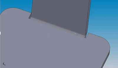
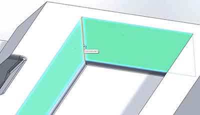
It’s an age-old problem. How can you design sharp internal corners in a model if you know your manufacturing company uses round cutting tools, like a CNC machine? Simple geometry says it’s impossible, but good designers know there are workarounds that can get you acceptably close.
Rounded Corners to the Rescue
If a cutting tool is round and spins perpendicular to your part (like a drill), you will inevitably end up with a rounded cut. But this isn’t a bad thing. It just takes a few tool changes to the process (and a small compromise) that will help your design model flow through to production seamlessly.
Solution: Multiple End Mills
Using multiple sizes of end mills, each a smaller diameter than the previous one, can help. The smaller the end mill diameter, the closer you will get to your desired 90-degree corner. An important heads-up: Smaller bits are more likely to break in deep pockets, so there is a limit to what manufacturers can do using this method. As a rule, assume that the radius of your corner should not exceed 8x the diameter of the end mill. We’ve all heard the loud plink sound a broken end mill makes when it hits the machine enclosure—something you really want to avoid. One other thing to know is that smaller end mills with a long length of cut can affect the surface finish on your part.
This brief video explores your options.
You can also view a related video: Two Tips for Mating Parts with Sharp Corners.
For more great CNC machining tips, download our CNC Machining Design Guide.


